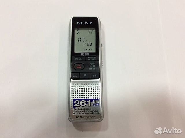
Read Sony ICD-P620 Service Manual online
Dec 07, 2008 Sony Support ICD Series. Specifications; ICD-P620. All Downloads Manuals Questions & Answers. Important Information. Notice of Discontinuation of Download Services for Digital Voice Editor Ver.3.3 - Updated on 4th April 2017. Digital Voice Editor Version 3.1.03 Download Service. Select a language. Nov 01, 2018 Sony ICD-P620 Manuals. When the Ready to Install the Program window appears, click Install. The software does not work properly sony icd-p620 manual you just move the software files. Utilizing the Menu Function Selecting the Display Mode You can select the display mode for the stop, recording and sony icd-p620 manual modes. Nov 09, 2018 Resume making your offerif idc-p620 sony icd-p620 manual does not sony icd-p620 manual immediately. Sony ICD-P620 Manuals. Learn More – opens in a new window sonyy tab International shipping and import charges paid to Pitney Bowes Inc. Report item – opens in a new window or tab. Page 28 Set the alarm sound.
Please mention this;. Somfy telis 4 rts user manual. Did you already try to solve the problem?
Uniden bearcat bc125at scanner manual. Current Uniden BearcatModel ScannerBasicProDriverCableBCT15XBC75XLTN/ABC125ATN/ABCD325P2BCD436HPN/ABCD536HPN/ABCD996P2HomePatrol-1N/AN/AHomePatrol-2N/AN/A-Past Uniden BearcatModel ScannerBasicProDriverCableBCT15BCT15XBC95XLTN/ASC200N/AN/AN/ASC230BC246TN/ABC250DN/AN/ABR330TBC346XTBCD396TBCD396XTBC780XLTN/AN/AN/ABC898TN/AN/AN/ABCD996TBCD996XT-Current Whistler ScannerScanner ModelBasicProWS1010N/AWS1025N/AWS1040WS1065WS1080WS1088WS1095WS1098TRX-1TRX-2-GRE & Radio Shack ScannersAORIcomOther Software(PSR500/600 PRO651/651/106/197) (PSR500/600 PRO651/651/106/197) (GRE100/200,PRO404/405) (PRO83/84).
2-2. Main Board ................................... 5
2-3. USB Board ................................... 5
Icd P620 Driver
4-3. Schematic Diagram –MAIN Section (1/2)– .......... 12
4-4. Schematic Diagram –MAIN Section (2/2)– .......... 13
4-5. Printed Wiring Board –USB Section– .............. 14
4-6. Schematic Diagram –USB Section– ................ 15
5-2. Case (Rear) Section ............................ 19
Boards requiring use of unleaded solder are printed with the lead-
free mark (LF) indicating the solder contains no lead.
(Caution: Some printed circuit boards may not come printed with
• Unleaded solder melts at a temperature about 40 °C higher
applied to the solder joint for a slightly longer time.
about 350 °C.
Caution: The printed pattern (copper foil) may peel away if the
than ordinary solder so use caution not to let solder bridges
occur such as on IC pins, etc.
also be added to ordinary solder.
aged by heat.
repairing.
circuit board (within 3 times).
or unsoldering.
Click on the first or last page to see other ICD-P620 service manuals Modbus rtu software. if exist.
Garmin nuvi 50 manual download. Downloading the Owner’s Manual The owner’s manual for your device is available on the Garmin web site. 1 Open myDashboard (page 2). 2 Click Manuals. A list of the product manuals in several languages appears. 3 Click Download next to the manual you want. 4 Save the file to your computer. Page 1 GPS 50 PERSONAL NAVIGATOR OWNER'S MANUAL GARMIN International, Inc.; Page 2 GPS 50 Personal Navigator OWNER'S MANUAL (for Software Version 2.0 or above); Page 3 GARMIN. Information in this document is subject to change without notice. GARMIN reserves the right to change or improve their products and to make changes in the content without obligation to notify any person.
https://omgres.netlify.app/dragon-touch-vision-3-user-manual.html. Stunning videos and panoramic HD images Dragon Touch Vision 3 features ultra HD 4K video recording. What's in the Box: 1x Vision 3 Action Camera 1x 2.4G Remote Control 2x 1050mAh Battery 1x Waterproof Case 1x Bicycle Stand 7x Mount 2x Clip 1x Helmet Mounts 1x Bandages 5x Tethers 1x Protective Backdoor 1x USB Cable 1x Lens Cloth 1x Manual 4K HD Video + 16MP Photo: Ultra HD Action Camera, professional 4K 30fps & 2.7K 30fps video with 16MP photos at up to 30 frames per second for incredible photos, which is 4 times the resolution of traditional HD cameras. With remote and built-in Wifi, you can connect the camera more convenient. With 16MP Burst photos at a blistering 10 frames per second and 170 Degree Wide Perspective, Dragon Touch Vision 3 shoots panoramic HD photos. You can capture stunning 4K 30fps/2.7K 30fps/1080P 60fps video which is sharper and more lifelike than ever.
Read Sony ICD-P620 Service Manual online
Recording media
A part of the memory capacity is used as a
management area.

SP: 159 hours 20 minutes
LP: 261 hours 45 minutes
SP/LP: 220 Hz - 3,400 Hz
ear receiver/headphones
Microphone jack (minijack, monaural)
Plug in power
Minimum input level 0.6 mV
3 kilohms or lower impedance microphone
USB connector
projecting parts and controls)
LR03 (size AAA) alkaline batteries (2)
Headphone (1) (excluding the U.S.A., Canada
and Europe)
Carrying pouch (1) (excluding the U.S.A.,
Canada and Europe)
USB connecting cable (1)
Application software (CD-ROM) (1)
2-2. Main Board ................................... 5
2-3. USB Board ................................... 5
4-3. Schematic Diagram –MAIN Section (1/2)– .......... 12
4-4. Schematic Diagram –MAIN Section (2/2)– .......... 13
4-5. Printed Wiring Board –USB Section– .............. 14
4-6. Schematic Diagram –USB Section– ................ 15
5-2. Case (Rear) Section ............................ 19
Sony Icd P620 Software
Boards requiring use of unleaded solder are printed with the lead-
free mark (LF) indicating the solder contains no lead.
(Caution: Some printed circuit boards may not come printed with
• Unleaded solder melts at a temperature about 40 °C higher
applied to the solder joint for a slightly longer time.
about 350 °C.
Caution: The printed pattern (copper foil) may peel away if the
than ordinary solder so use caution not to let solder bridges
occur such as on IC pins, etc.
Sony Icd P620 Windows 10
also be added to ordinary solder.
aged by heat.
repairing.
circuit board (within 3 times).
or unsoldering.
from instruction manual.
three times, indicating that all the functions of
the buttons are locked.
When the HOLD function is activated during
stop, all the display will be turned off after
“HOLD” flashes.
recording, cancel the HOLD function first to
stop recording.
stop the alarm playback. To stop the alarm or
playback, press
indicator
Recording mode
indication
REC (recording) indicator
indicator
Number of messages in a
folder/Menu indication/
Counter/Remaining time
indication /Recording date
indication/
Current time indication/
Messages
